Julius Elbridge Steele
- Born: 16 Feb 1827, Berlin CT
- Marriage (1): Rebecca Eddy on 22 Feb 1848 in New Britain CT
General notes:
Jeweler and engraver
Events in his life were:
- Apprenticed: CHURCHILL & STANLEY, about 1850, in New Britain CT.
- He worked circa 1860-1880 as a jeweler and engraver in New Britain CT
- He appeared on the census in 1860 in New Britain CT. Listed as a jeweler.

- Patent: 7,578, on 21 Jul 1874. ELBRIDGE J. STEELE, OF NEW BRITAIN, ASSIGNOR TO SARGENT & CO., OF NEW HAVEN, CONNECTICUT.
DESIGN FOR TWINE-HOLDER.
Specification forming part of Design No. 7,578, dated July 21, 1874; application filed June 3, 1874.
To all-whom it may concern:
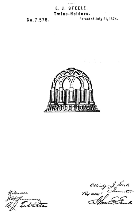
Be it known that I, Elbridge J. Steele, of New Britain, in the county of Hartford and State of Connecticut, have invented a new Design for Twine-Holder; and I do hereby declare the following, when taken in connection with the accompanying drawing and the letters of reference marked thereon, to be a full, clear, and exact description of the same, and which said drawing constitutes part of this specification, and represents a perspective view.
This invention relates to a design for a box or case for holding a ball of twine; and it consists in the peculiar configuration and ornamentation of the case, as shown in the accompanying illustration, and more fully hereinafter described.
The general outline transversely is circular. The base is of ogee-form, around the upper edge of which stand a succession of columns, connected at the top by intersecting arches, drawing in to form a dome-shaped top, ail as shown in the accompanying illustration.
I claim as my invention—
The design for twine-holder, consisting of the base, vertical columns standing thereon, and connected at their upper ends by intersecting arches in dome form, as shown in the accompanying illustration and hereinafter described.
Elbridge J. Steele
Witnesses:
Henry Nash
L. M. Smith

- He was issued patent number 184,184 on 7 Nov 1876
ELBRIDGE J. STEELE, OF NEW BRITAIN, CONNECTICUT, ASSIGNOR TO HIMSELF AND THE STANLEY WORKS, OF SAME PLACE
IMPROVEMENT IN DOOR-BOLTS.
Specification forming part of Letters Patent No. 184,184, dated November 7,1876
To all whom it may concern:
Be it known that I, Elbridge J, Steele, of the city of New Britain, in the county of Hartford and State of Connecticut, have invented certain new and useful Improvements in Door-Bolts, of which the following is a specification:
The invention relates to an improved door-bolt, the body of which is of wrought-iron, and the front of which is of bronze metal, all as hereinafter described; and is adapted to that class of bolts whose front is let in flush with the surface of the door to which they are applied.
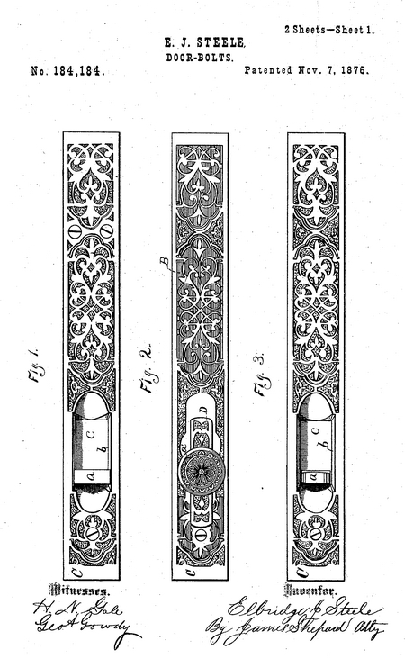
In the accompanying drawing, Figures 1, 2, and 3 are front elevations of door-bolts, which embody my invention, and Figs. 4 and 5 are central longitudinal sections of the same.
In Figs. 1, 3, and 4 the operating-handle a of the bolt A, Fig. 4, is let in flush with the surface of the outer plate. The main plate B is of plain wrought - iron, whereby great strength and durability, as well as cheapness of construction, are obtained. Underneath the main plate B the bolt A is fitted to slide, and is provided in the ordinary manner with a friction-spring (not shown) to hold it in or out when put in either of said positions. Over the front surface of the main plate B, and, if desired, over the end surface also, I place an ornamental or supplementary cap - plate, G, preferably of bronze metal, thereby giving the article all the appearance of a solid bronze bolt, and leaving the article free from all the disadvantages of such bolt. In the main plate, near the handle a, there is an opening which receives the bottomless depression b of the supplementary cap C, which depression b is wide enough to receive the handle a, and long enough to give said handle the requisite longitudinal movement for throwing the bolt. The portion of the bolt B under the depression b, is provided with a face, e, of the same material as the cap C, or finished so as to correspond therewith. The supplementary cap-plate C may be riveted or otherwise secured to the main plate B, in which case the handle a may be of such form and size as to support the rear end of the bolt A by working against the beveled sides of the depression b, as shown in Fig. 1, and in which case the handle could be permanently secured to its bolt, as shown in Fig. 1, and the completed bolt may be secured to the door by screws, which pass through both the cap and main plate. In such a construction of the handle and cap-plate, the bridge or staple d, Fig. 4, can be dispensed with, if desired, and it is optional whether the cap shall cover the front only, as shown in Fig. 4, or the front and end, as shown in Fig. 5.
When a door is to be painted, and in other cases, it may be desirable to remove the supplementary cap without removing the bolt proper, the styles shown in Figs. 2, 3, and 5, are adapted for such purpose. Fig. 3 differs from Fig. 1 in the fact that the rear end of the bolt is guided or supported by the bridge d, Fig. 4, instead of by the handle a, and that said handle is of a size that will readily pass through the depression b.
The supplementary cap-plate is secured to the main plate at the handle end by means of a small screw, and at the opposite end by means of the end of the bolt and a screw. By removing the two said screws the cap may be removed for painting the door or other purpose, such. as polishing the cap, and. all the operative parts of the door-bolt remain secured to the door. When the cap covers the end, as in Fig. 5, the bolt is made of such length that when drawn inward to its full capacity the outer end will project from the main plate just the thickness of the cap-plate, which has a hole formed in it of a size to correspond with the end of the bolt so that the latter serves to aid in holding the cap in place. A screw may also pass through the hole e, Fig. 5, in both cap and plate, to further secure the parts.
In Figs. 2 and 5 a projecting handle, a', is shown. The cap is removable without removing the main parts of the bolt, and is secured by a small screw near the handle, and another at the outer end through the hole e, Fig. 5. A small plate, D, covers the opening in the main plate, through which small plate the handle a' passes, and is screwed into the bolt so that it can readily be removed for the purpose of taking off the supplementary cap-plate. The cap-plate shown in Fig. 2 is what may be termed an open-work or skeleton plate, the main plate
underneath it showing through the openings, but the ornamentation is immaterial, and the cap plate may be finished and ornamented in any manner desired.
Bronze metal, although desirable on account of its neat finish, is not strong and durable like wrought-iron, and in order to make it of the requisite strength for a door-bolt they must be made quite heavy, thereby greatly increasing the cost. By making the body of the bolt of wrought-iron and finishing it with a bronze cap, I produce a bolt at a much less cost than a bronze metal bolt, and at the same time one that is much better, because stronger, and yet retaining all that is desirable in a bronze bolt.
I claim as my invention—
1. As a new article of manufacture, a door-bolt consisting of the bolt A B and supplementary cap-plate C, substantially as described, and for the purposes specified.
2. The combination of the projecting end of the bolt A, and the cap-plate C extending over the end of the bolt, and having an opening in it which corresponds to the end of the bolt, substantially as described, and for the purpose specified.
3. The removable cap-plate C, having a depression, b, large enough to admit the handle a, Fig. 3, in combination with said handle, the main plate B, and bolt A, whereby said cap-plate may be detached without detaching the other parts of the bolt, substantially as described.
Elbridge J. Steele
Witnesses:
James Shepard
G. L. Reynolds
- He appeared on the census in 1880 in New Britain CT. Listed as an engraver.
Julius married Rebecca Eddy on 22 Feb 1848 in New Britain CT. (Rebecca Eddy was born on 27 Apr 1829 in New Britain CT and died on 21 Feb 1909 in Naugatuck CT.)
|


